![]() Further reports:
Further reports:
Summer 2023
Winter 2022/23: Working on the turret
Winter 2021/22 and summer 2022: Working on the turret
Winter 2020/21 and summer 2021: The electrical system and hull
Winter 2019/20 and summer 2020: Turret and the electrical system
‘Seeing this alone was worth the entrance fee’
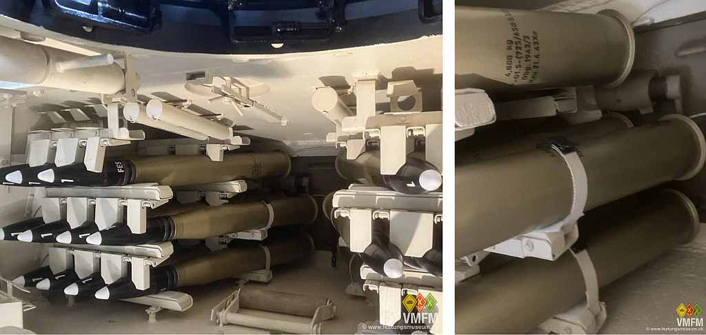
…said Jeff Gagliardi from Orange County / California, when visiting our museum with his father-in-law and having a glance at the restored and filled ammo racks. That’s a statement we don’t hear everyday.
For the pleasure of it, here again what inspired him:
 The way to that state was reported in the previous report.
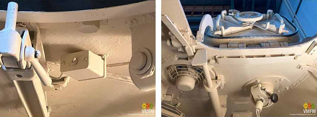
The only work inside the turret during this summer were at the turret roof.
Next to the turret fan sits the on / off switch which we recreated with the help of images from other tanks. The interior was improvised. Furthermore we had to re-adjust the damper and locking mechanism of the loader’s hatch since a proper and safe operation was not given..
 The major part of the summer work revolved around the turret traverse and the parts belonging to it.
After performing major welding actions to restore to rear part of the traverse frame during the previous season we could now install the container for the pressurized air which blows out the smoke after firing. Attached to it, under a flap behind the cylinder, is a pressure release valve. This valve was broken off and in a very poor condition. We disassembled and cleaned it and were able to revise it, though it will never again release excessive pressure.
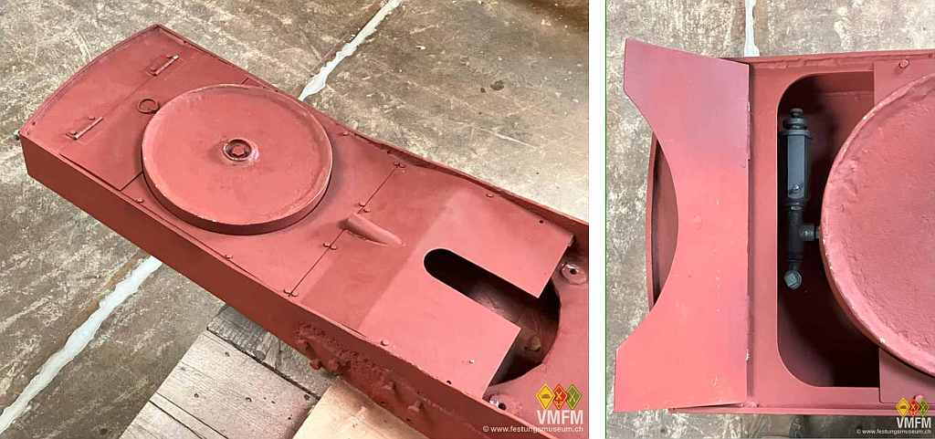 Björn has CNC-cut the thin sheet metal covers for the rear section of the traverse and fitted them in painstaking detailed work as the cylinder was not completely round and the traverse frame was not completely symmetric.
The most extensive and complex project of the season, in fact, was the revision of the hydraulic drive motor for turning the turret. Actually, it has been heavy on my mind for a couple of years. I was me who has disassembled it enthusiastically and stored all parts in boxes and plastic bags. Unfortunately, only afterwards I learned that many interior parts were individually measured against each other and must not be confused with similar looking pieces. Too late.
It is a so-called Boehringer-Sturm oil drive motor and is infinitely variable. It is positioned in the middle of the turret traverse and is powered by the engine via a lamella clutch. The downforce is linked to the traverse drive by a toothed gear unit. The traverse drive moves the turret gear ring.
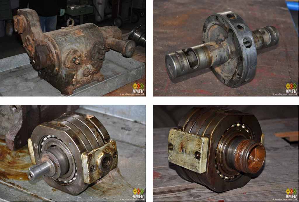 The drive motor consists of a cast housing, the oil filling and a central hollow axis which holds two identical rotary vane pumps units at each end. Each unit consists of a cylinder with 7 vanes, the circulating housing ring it rotates in and two lids for the housing.
The unit on the entrance side is powered by the engine and is called oil pump. This pump presses oil through the axis and drives the front unit which is called oil motor.
So far, so simple.
Matters become complex by the fact that the housing ring with the vanes can be shifted off-center towards the central cylinder to the left and right, generating variable displacement volumes.
A shifting of the oil pump to the left or right, as executed by the gunner by either pressing a foot pedal to the left or right or manipulating a handle at his seat up or down, will cause the turret to turn left or right. The higher the eccentricity, the faster the rotation.
The extent of the off-centering of the oil motor impacts speed and torque for fine adjustment of the turret direction.
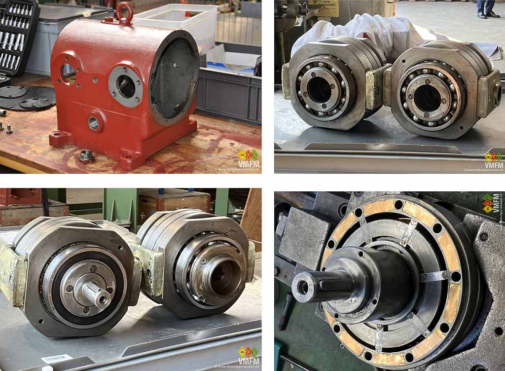 Unfortunately, the central axis was damaged in the course of disassembly and had to be revised by precise welding, metal application and subsequent fine grinding.
Most parts were in a remarkably good condition, only one circulating housing needed to be made new due to excessive corrosion on the inner side.
During assembly it became obvious that, despite using the original and correct parts, the units were too tight and could not be moved off-center.
In this situation the company Fa. Spitznas Maschinenfabrik in Velbert / NRW, and in particular Stefan Rohde proved to be of valuable help. The company services modern derivatives of this gear type.
Among other things we learned that the inner surface of the lid needs to be surface grinded every time after shrink-mounting the bearing on the outside. We were unable to conduct that and also Spitznas didn’t have the necessary tools available any more. In order to generate the necessary clearance between housing and lid, we cut brass foil of 0.05 resp. 0.075 mm to appropriate pieces and positioned them between housing and lid. We preferred a minor traction slip within the pump units to the risk of major damages from too tight units.
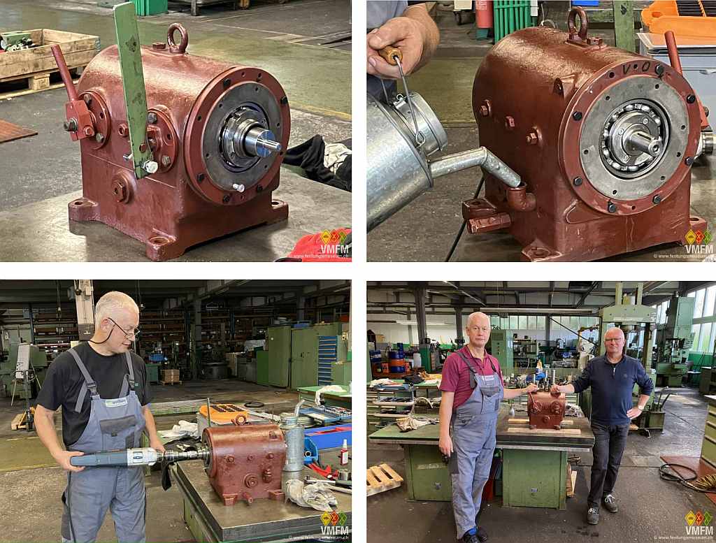
After tedious trials we eventually succeeded in re-assembling the drive motor and arrange a run on the test booth at Spitznas. An initial test with an electric drill proved satisfying. On the next morning Stefan and me were equally excited and listening for suspicious sounds after starting the run.
To make a long story short: The test was successful and relief was seizable.
See two short spots about mode of action and test run: